The Wiki-INPRO (under development)
The International Project on Innovative Nuclear Reactors and Fuel Cycles (INPRO) was established in 2000 to help ensure that nuclear energy is available to contribute to meeting the energy needs of the 21st century in a sustainable manner.
This Wiki is an initial attempt to formulate in a structured manner the accumulated experience and knowledge on the concepts, ideas, and methodology relevant to the INPRO domain.
The content of the Wiki is an opinion of the expert community and does not represent the official position of the IAEA, unless explicitly mentioned or referenced from a relevant IAEA publication.
Introduction
INPRO derived its concept of a sustainable development of nuclear energy from the United Nations (UN) sustainable development concept issued in the 1987 Report of the World Commission on Environment and Development. The following is the reports definition for sustainable development.
“Sustainable development is development that meets the needs of the present without compromising the ability of future generations to meet their own needs”.
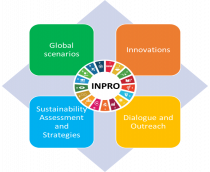
A sustainable energy supply is an important requisite for a country to obtain sustainable development. Nuclear energy is one option for sustainable energy supply system. INPRO is an IAEA forward looking project that integrates all areas important to sustainability of nuclear energy. There are four tasks in INPRO for sustainability of nuclear energy systems, as shown in Figure 1; these are global scenarios analysis, role of innovations in sustainability, sustainability assessments and strategies, and outreach and dialogue. Figure 2 captures the essence of INPRO task areas.
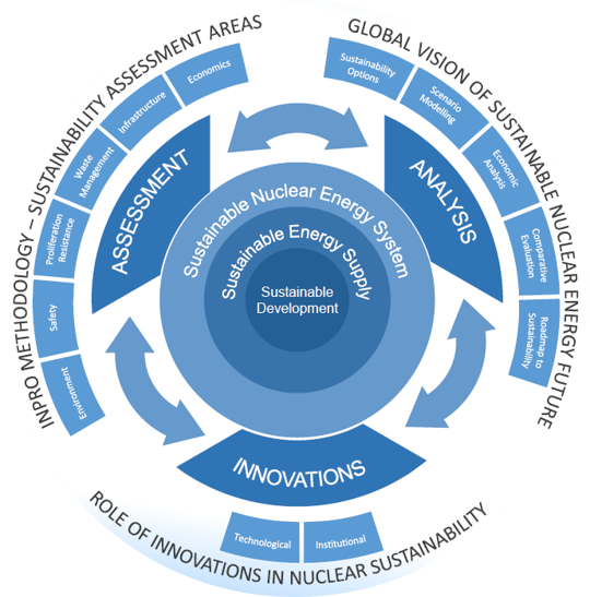

Based on the UN concept of the sustainable development, INPRO developed the INPRO methodology for detailed assessment of sustainability of nuclear energy systems. In the INPRO methodology, a nuclear energy system is considered as sustainable if it contributes or at least can contribute to the sustainable development on the national, regional or global level.
The INPRO methodology ensures that a given nuclear energy system takes into account the four dimensions of the UN's concept of sustainability: environmental, social, economic and institutional.
To address specific issues related to the development and deployment of nuclear energy systems (NES) for sustainable energy supply, INPRO has identified six topical areas of relevance to NES sustainability assessment, including economics, environmental impact, safety, proliferation resistance, waste management and infrastructure.
The methodology helps to identify the sustainability related gaps in the existing or planned nuclear energy system.
Innovations help to fill these gaps. The development of both technical and institutional innovations is necessary for nuclear energy to play a sustainable role in the global energy supply. This INPRO activity aims to support the investigation of innovative nuclear energy technologies, related RD&D and institutional arrangements which can be instrumental in developing sustainable nuclear energy system.
INPRO has developed a service for Member States "Analysis Support for Enhanced Nuclear Energy Sustainability (ASENES)". The main purpose of this service is to assist and guide Member States on scenario development and analysis, comparative evaluation of nuclear energy system/scenario options and road mapping to support strategic planning towards enhanced nuclear energy sustainability.